


![UNO R4 WiFi [ABX00087] - Renesas RA4M1 + ESP32-S3, Wi-Fi, Bluetooth, USB-C, CAN, 12-bit DAC, OP AMP, Qwiic Connector, 12x8 LED Matrix for Advanced IoT & Embedded Projects](https://m.media-amazon.com/images/I/614tXIQWSRL._AC_UY218_.jpg)


I obviously do a lot of Steampunk projects, but there are a ton of things out there that I haven't tried yet. So, in an effort to broaden my horizons, I recently taught myself how to use Arduinos, which I plan to incorporate into some of my future Steampunk builds.
Since there will be some Arduino-related projects in Steampunk R&D coming soon, I decided to write this basic guide for how to use Arduino microcontrollers, so that I (and you) can refer back to it in the future.
This guide is specifically for people who are too intimidated to start using an Arduino, and wouldn't even know where to start if they wanted to. In fact, my ideal reader may not even have a solid idea of what an Arduino is.
So, let's start there.
What IS an Arduino, Anyway?
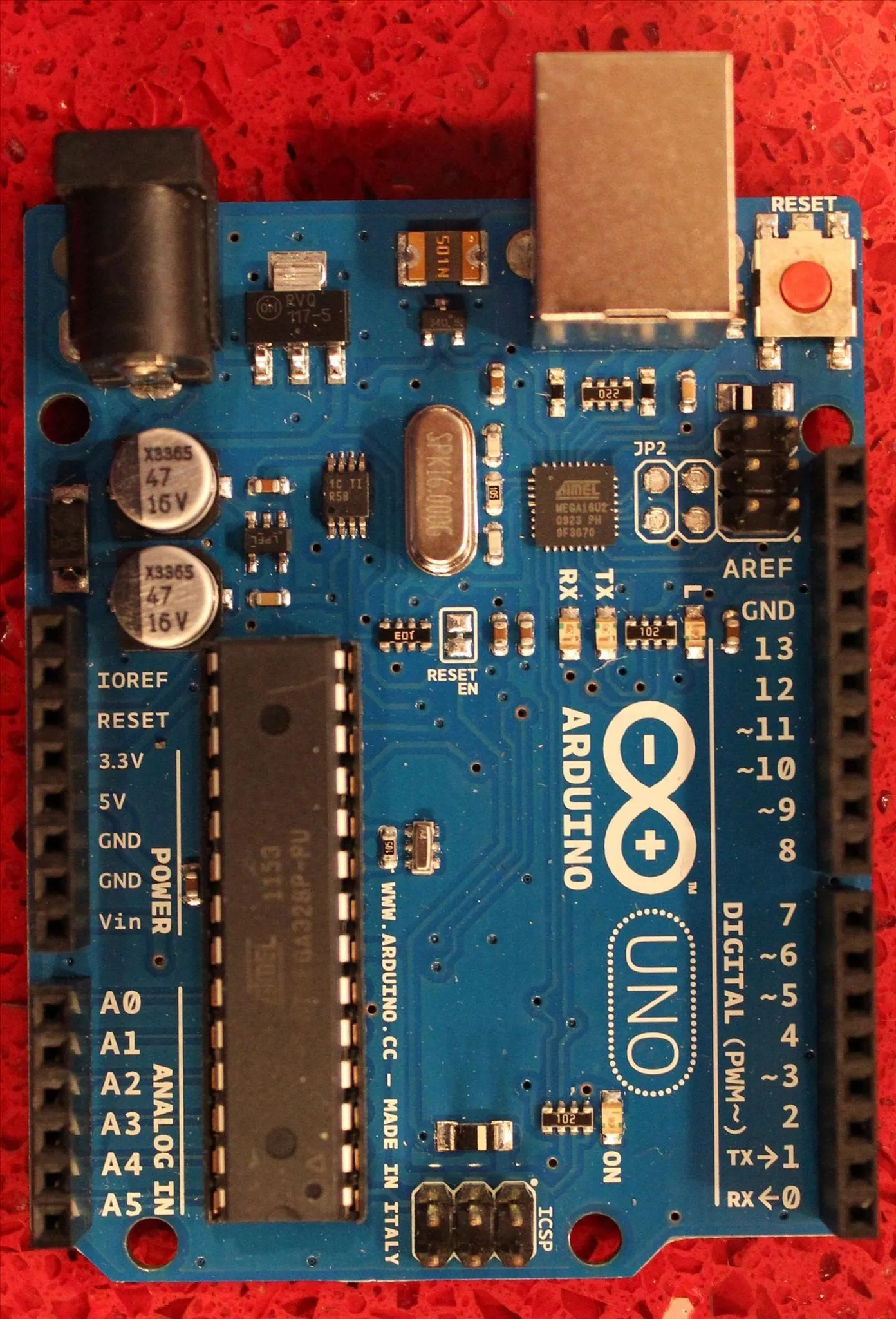
Well, this is an Arduino:
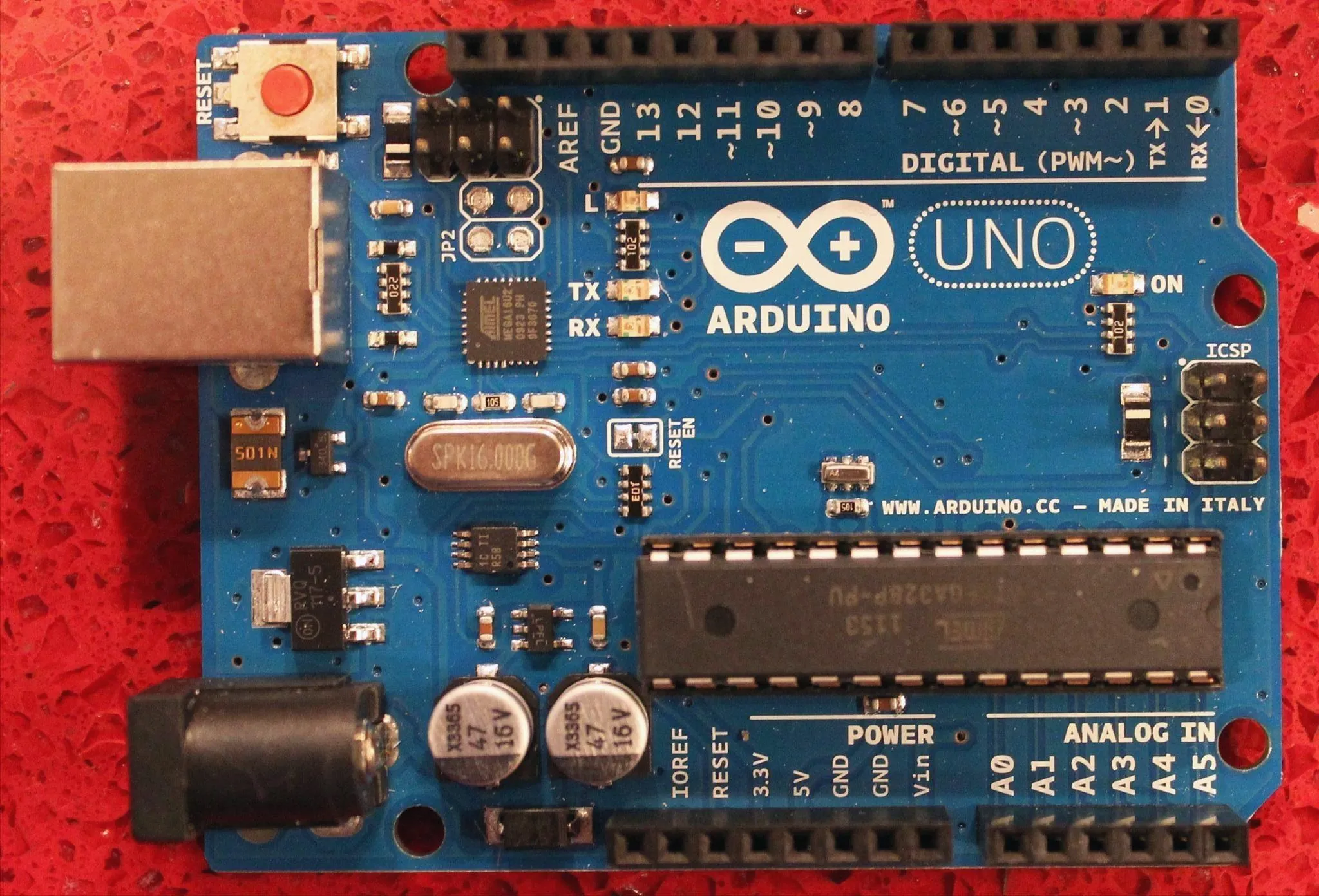
As you can see, it's a little board that's got electronic stuff all over it, along with a bunch of holes on the sides, and a bunch of writing that doesn't make any sense (yet). Also, it says "Made in Italy", because Arduino is Italian. It's named after the town in which it was created, and it means "Brave Friend" in Italian.
The Arduino is an open-source microcontroller board, which probably doesn't mean anything to you. It didn't mean anything to me until recently either, so no worries. Being open-source means that anyone can write code for it, basically, and a microcontroller is a board that provides a platform from which one can use a variety of hardwares.
Bear in mind that these are pretty simplistic definitions, but that's really all you need at this stage.
In layman's terms, this means that you can run code on this platform (the Arduino), and that code will control whatever hardware you attach to it, provided that they're compatible. Before we get into that, let's discuss the most important parts of the Arduino. Well, the most important parts to you.
The Holes in the Board
As you saw in the above picture, there are lines of holes running up and down either side of the board. You'll be sticking things in those holes.
There are two other holes you may be sticking things in, and that's the two on the front of the board:
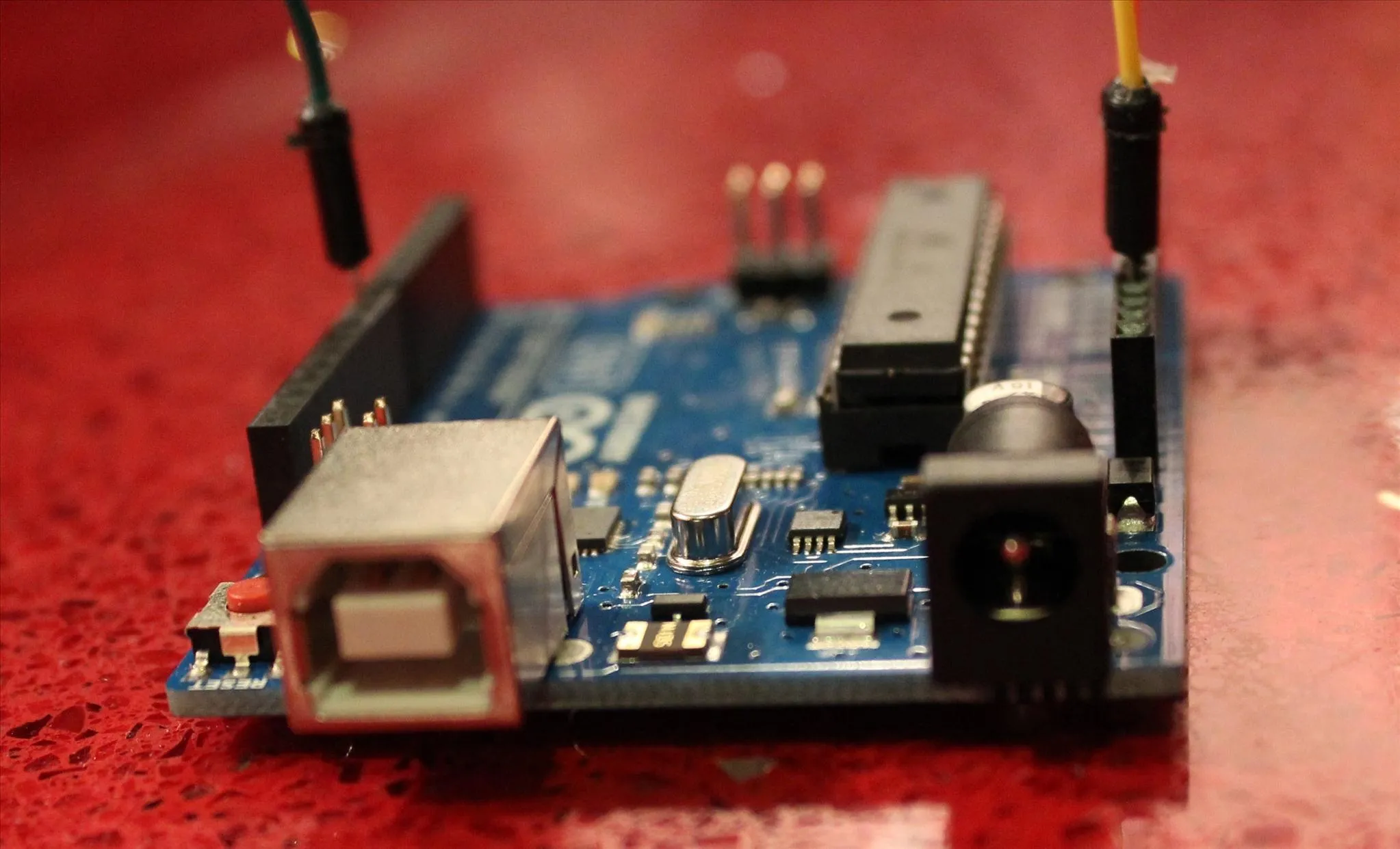
While it's not as in-focus as I'd intended, you can see two places where you can plug things in. Generally you'll use the left one to attach a USB plug and thereby to your computer, and you'll use the right one to power your board when it's away from your computer by using either a wall plug or batteries.
By uploading code onto the board via the left plug, you can use it to control whatever hardware you attach to the little holes on the left and right. That's what an Arduino is!
But... How Do?
Alright, so now you know what an Arduino is and what it does. The next (and hardest) step is to show you how it does it.
Because there's a thriving development community for Arduinos on the internet, you can probably find code and circuit diagrams for nearly any project you want to make. However, that requires you to be able to read code and understand circuit diagrams, so that's what we're going to do.
Before we get there, though, I want to recommend that you buy the set that I did. That's the Arduino Inventor's Kit. It's a little pricey, but it has all the parts you should need to get started with using Arduinos. It's the kit that I used to teach myself how to use them, and it's really great. It can be confusing at first, though, which is why I'm writing this guide instead of just saying, "Hey, just go buy this kit."
So if you want to learn how to use Arduinos but don't know where to start? Buy that kit. That's where you start. Well, after here, of course.
The Breadboard
Alright, let me introduce you to the humble breadboard:
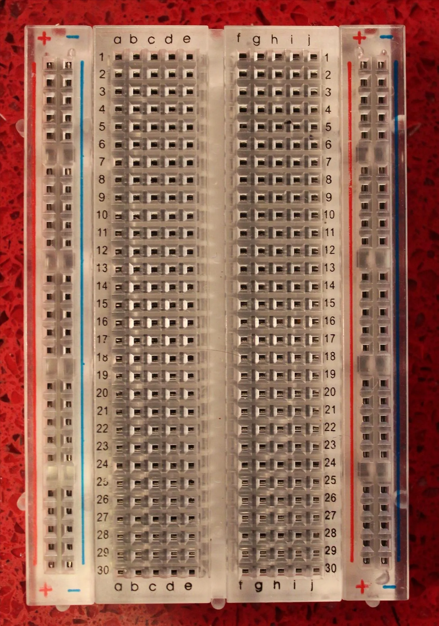
As you can see, it is only kind of a board, and it certainly isn't made of bread. They're called that because at one point, they were literally made of boards that were used for cutting bread. Technology has come a long way, though, and now we have these boards that you can just plug things into.
Speaking of plugs, let me take a moment to show you these wires. You can use a regular wire and just strip the ends, but the Inventor's Kit comes with a few of these:
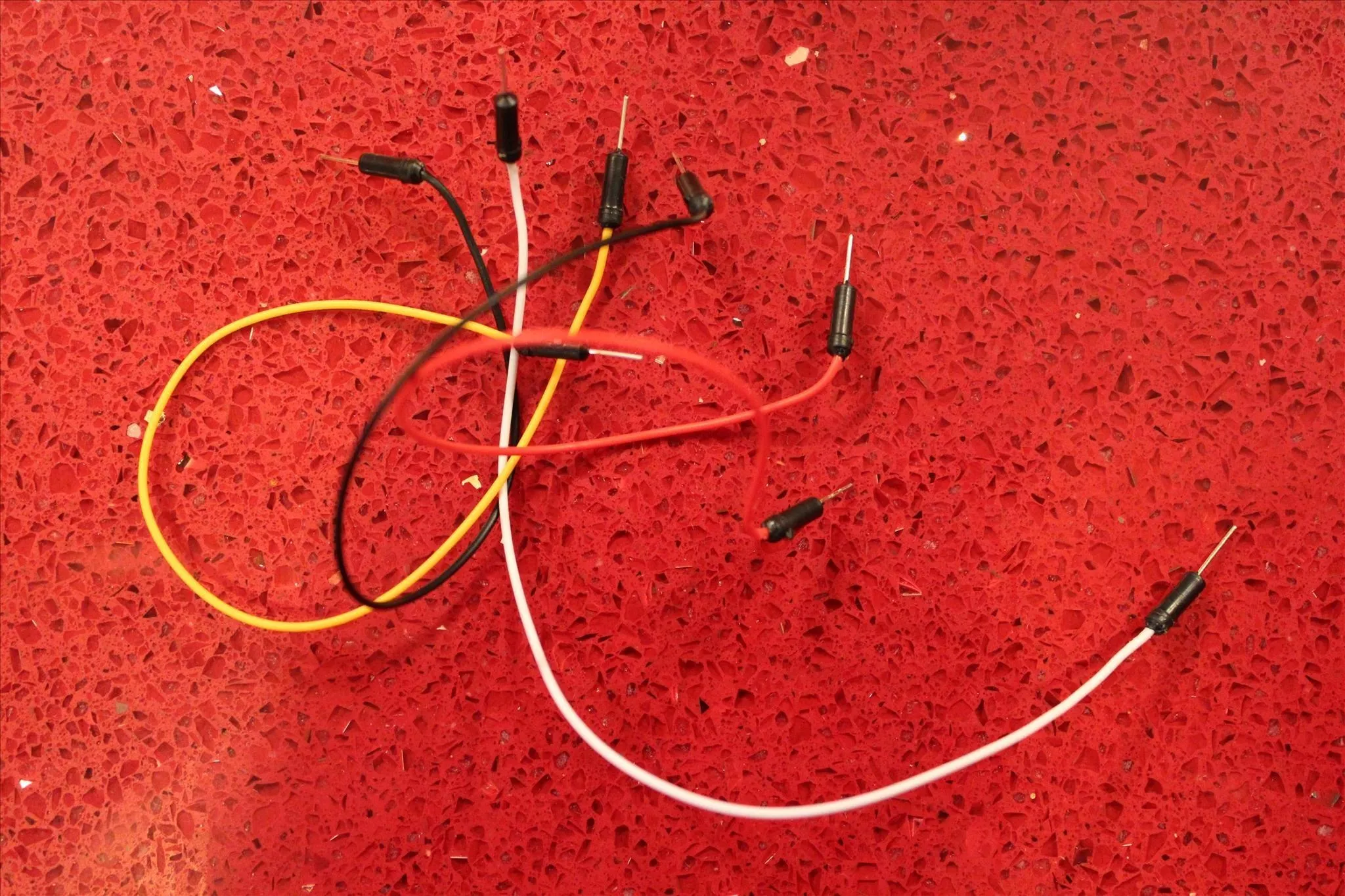
They're wires with little plug-y end bits built on. Like I said, you can just strip the insulation from regular copper wires, but these are easy because they come pre-cut and pre-stripped. Also, they're colored, so it's easy to tell them apart.
Now that I've shown you those two things, let me take a moment to de-mystify the breadboard for you. It looks complicated, with its letters and numbers and whatnot, but it's really quite simple. The breadboard is really just a shortcut, that's all. You don't need it, but it will allow you to test circuits without having to solder them together. Soldering, if you don't know, is when you bind a specific type of metal around something to hold it together, frequently used on the tips of wires. The board creates specific electrical connections between its holes so that the wires don't have to be soldered.
The only trick you need to know is where those connections are. With the help of Photoshop, I will show you! Below is a picture of a breadboard on which I have highlighted a few things that I'll be talking about underneath. Hope you're not color-blind!
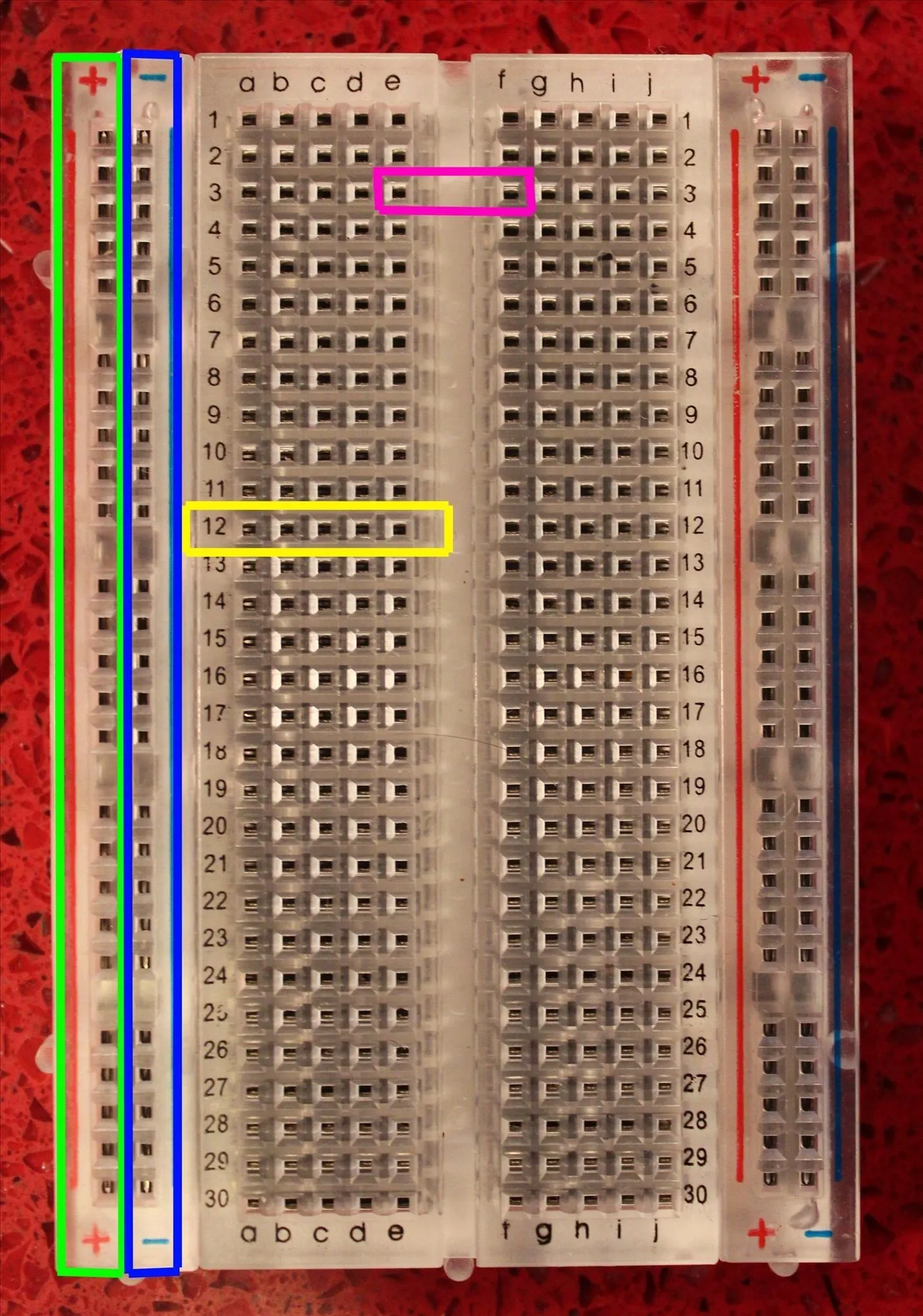
So, I've drawn rectangles around four different locations on the board. Those four colors are green, blue, yellow, and pink.
- Yellow: Inside the yellow box are five plugs that are all connected to each other. For example, if you plug a wire into the 'A' plug on the far left and another wire into the 'E' plug on the far right, those two wires will have a connection. Any wires you plug in anywhere else on the board will not be connected to the wires in row 12 (inside the yellow box). The plugs in each half-row are only connected to themselves, and nowhere else.
- Pink: If you connect these two holes with a wire, the connection will extend into the row across from it. While the rows on the left and right side of the board share the same numbers, they are not connected. If you want them to share a connection, you need to bridge the gap with a wire.
- Green and Blue: All the plugs in the green box are connected to each other, and all the plugs in the blue box are connected to each other. These provide areas for you to control the flow of power. Each circuit is going to have at least one wire attached to a plug in the green box, and one wire attached to a plug in the blue box. Think of them as the sides of a battery.... The power flows from one end, through the device, to the other end. Without a completed circuit, nothing will happen and the power won't flow. For the record, the green box (with the plus sign) is known as a Cathode, while the blue box (with the minus sign) is known as the Anode. You don't need to remember that, I was just letting you know.
Again, this is just a shortcut for actually soldering the wires to their respective locations. If you plan to incorporate the Arduino into a build of some sort, you absolutely don't want to use a breadboard, but instead you want to just solder all the parts together. However, the breadboard is a great teaching tool.
Putting Together a Circuit
So, now you know what an Arduino, breadboard, and wires are. Time to combine them into a circuit!
What I've done is taken a picture of one of the cards that came with my Arduino Inventor's Kit. This is a stylized picture of a breadboard, and I'll explain it to you below:

By plugging things into your breadboard as it suggests, you can have a circuit that will allow you to make an LED (light-emitting diode) blink. So, this is pretty self-explanatory, though it may be a little confusing so I'll tell you exactly what it all means. First, let me show you the two parts it requires that you aren't yet familiar with.
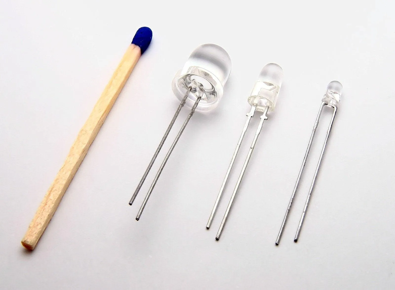
These are LEDs below. Note that one of the metal bits poking out of their bottoms is longer than the other. That's important.
The other thing is a resistor, a packet of which looks like this:
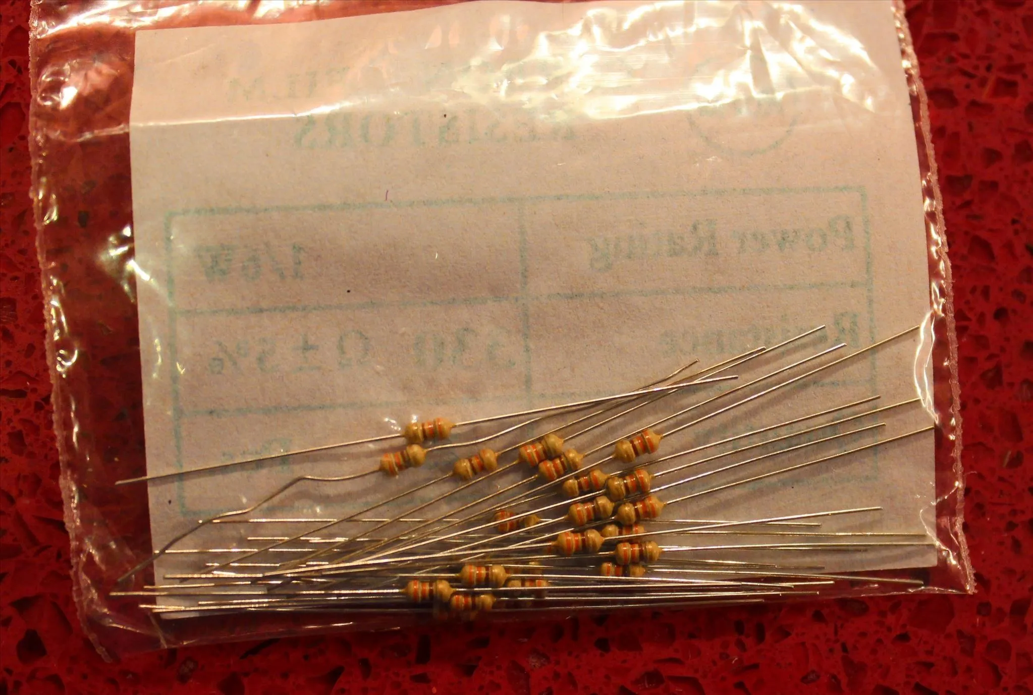
Resistors are kind of complicated, and in order to fully understand them, I'll have to explain things like current and voltage. However, considering that this is a beginner's guide, I'll skip over all the technical stuff. It is not required to understand circuits in order to use Arduinos!
Why is that? Because the Arduino platform has so much support on the internet that you should easily be able to find a diagram telling you exactly what resistors you need where, in order to make a proper circuit. I'll give you a few good resources at the end of this article for that. But anyway, the above picture is what resistors look like. Note also that they have lines on them, and those lines also appear on the drawing above so that you know which direction the resistor should be installed.
So let's bring that photo back, now that you've seen the parts.
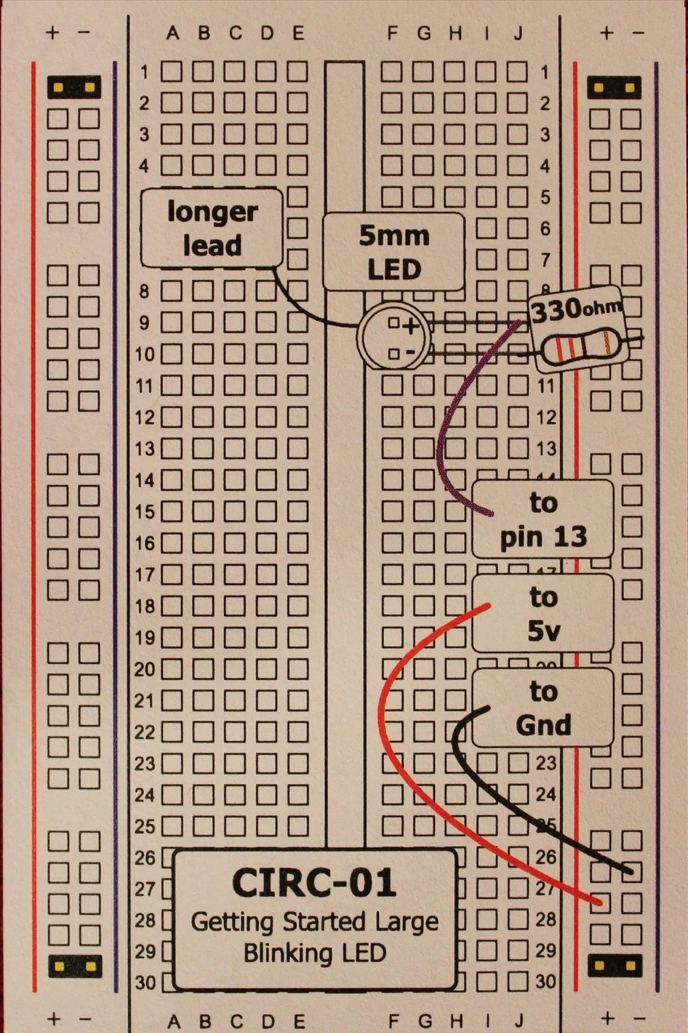
So basically what it's telling you to do is to plug your LED's longer metal thingie (lead) into row 9, and its shorter lead into row 10. A resistor (which is 330 ohms, as it tells you) then connects row 10 to the anode (the minus column). You can place the resistor in any hole on the minus column, because remember that they're all connected.
The rest is just wires going to the Arduino itself, so let's take a look. We have a wire going from row 9 to "pin 13", and then a wire on the cathode (plus sign) to "5v" and one on the anode going to "Gnd".
Here's the Arduino itself. Note how all the little holes are labeled. All you have to do is find the number 13 (on the right), 5v (on the left), and Gnd (also on the left) and plug the appropriate wires in.
So when you plug your wires into the correct holes, your LED will start to blink!
What's that? It's not blinking?
Of course it's not. Not only does your Arduino have no power, it also doesn't know to tell your LED to blink.
Let's learn how to tell it to make the LED blink!
Cut and Paste Coding
You don't have to know how to code, don't worry. In fact, the vast majority of coding you'll be doing will simply be cutting and pasting from the internet.
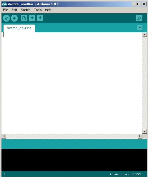
The very first thing you need to do, though, is to download the Arduino software from the official Arduino site. When you run it, you should get a screen like this:

And then a somewhat intimidating blank cursor like this:
Once this is open, go ahead and plug your Arduino into your computer's USB port. Presumably you have a USB connector. If you don't, you'd better get one, because you'll need it to go any further.
Now in order to get your light blinking, you'll need to input code that says "make this light blink!"
Thankfully, that's pretty simple code, and it's easy to find. In fact, they have this code freely available on the Arduino site here. Just highlight that code and paste it right into your Arduino program window, like so:
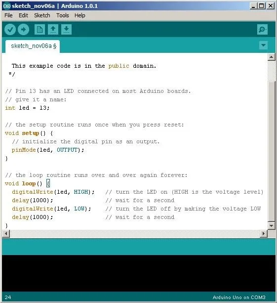
Whoa, slow down there! That's a lot of... stuff! It's got all of these slashes and colors and weird formatting!
If you don't panic and instead read it line-by-line, you'll find that it actually does a pretty good job of explaining exactly what it's doing. Any of the gray text that appears after the twin slashes (//) isn't code at all, but is there to tell you what's going on. First it's telling the Arduino that it has an LED attached to pin 13. Then it's initializing that pin.
After that, it gives the Arduino the details of exactly what it wants it to do. Turn the LED on high, wait 1000 milliseconds (better known as 1 second), then turn the LED on low (aka "off"). Then it waits another 1 second and repeats the whole process.
Assuming that we like the idea of our LED blinking on and off every second, let's go ahead and upload this to our board.
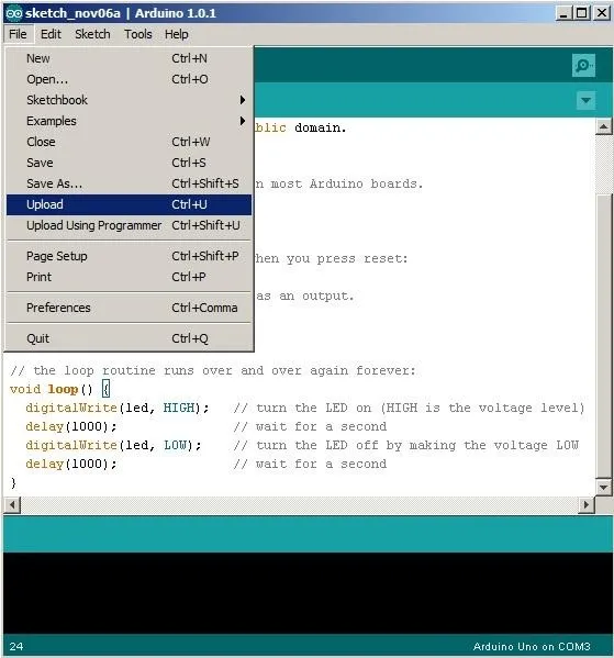
You'll have to select your Arduino board when you do this, but you should be able to manage that. Just make sure it's plugged in.
Once you select 'Upload', the program will get sent directly to the Arduino board. As soon as it finishes uploading, your LED will immediately start blinking! Congratulations!
Now as long as your board has power, it will continue to make that LED blink. If you want to get really crazy, you can go into the code and edit it to your liking. For example, try changing the delay(1000) to delay(200). It'll blink on and off several times a second. That's right, you can change the variables of the code without actually knowing anything about coding!
Isn't that brilliant?
You can even change which pin on the Arduino you use. For example, go ahead and move the wire from pin 13 to pin 7, and then change the code from int led = 13; to int led = 7; and voila, you've now discovered how to use different pins. In fact, if you wanted to plug LEDs into every pin and then just copied and pasted the code over and over again, changing the pin number each time, you would be able to make them all blink simultaneously.
Super easy!
All you have to do in order to make something work is to find a diagram for it, then find the code for it, and then just make it happen.
Circuit Diagrams
You won't always find simple breadboard charts like I showed. Far more often, you'll find a circuit diagram that will look something like this:
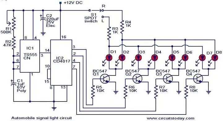
That probably makes absolutely no sense to you. If you're like me, it may even fill you with a sense of foreboding.
However, not to worry... This is the circuit diagram of our blinking LED:
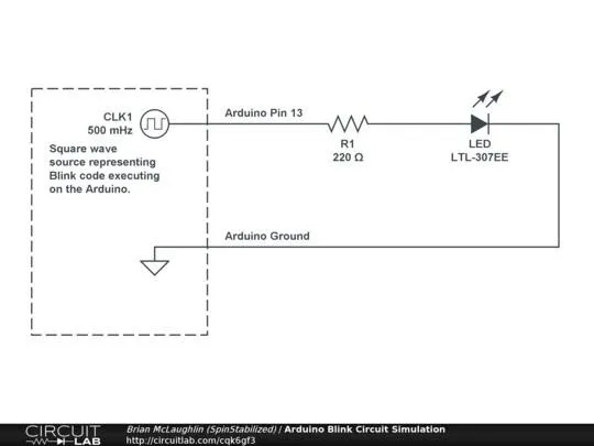
While I can't explain absolutely everything about circuit diagrams to you in this article (it would be far, far too long), the most important thing is understanding that in most cases, the lines only kind of represent real, physical wires.
The diagram traces the general path of the electricity, but, for example, you'll notice that while the above picture is a weird rectangle-y thing, our actual, physical circuit looked nothing like that at all.
Circuit diagrams look the way they do for the sake of clarity, not because you need to make your real circuit look like them. Instead, the only important parts are what connects where.
Again, look at the above diagram. It has a square wave representing the code we input. Then it has some zigzag lines. Those zigzags are the standard symbol for a resistor, and it will generally say nearby what type it is. They used a 220 Ohm (Ohm/omega, see what they did there?) resistor, while we used a 330, but it's still the same circuit.
That leads to the LED, and then it grounds in the Arduino. That's what 'GND' stands for... 'Ground'. That basically gets rid of the extra power in the circuit, and every circuit needs to be grounded.
If you come across any symbols in a circuit diagram that you don't know, I recommend consulting Wikipedia, which is where I found this handy graphic:
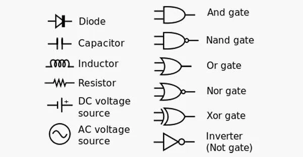
Working with Arduinos, you won't need any of the gates on the right, but you will definitely encounter the symbols on the left in more complicated projects.
The best part about the Arduino is that you don't have to know what any of those things do! You don't need to know what a capacitor is, or what a resistor does, or anything. Of course, if you want to make your own circuits, you'll have to do some serious research for it, but like I said, nearly any circuit you might need can be found on the internet with some good Google-fu.
In fact, here. These two sites should be enough to get you going:
If you find that you want to do a specific project that you can't find on either of those two sites, well, look no further than right here on WonderHowTo. I know that the Mad Science World even has a section devoted just to "Mad Arduino" projects, so make sure to check those out.
If you can't find something of interest on WHT, just do a web search for it; odds are good that someone has already tried it and written a tutorial somewhere.
Now that you know how to make connections and upload code, that's really all you need! Just apply that to any diagrams and code you find, and you can make practically anything!
I hope this has been helpful for those of you who were too intimidated to try learning how to use Arduinos, and if you make anything with them (even a blinking LED) please let me know!
And stay tuned for some cool Steampunk-related Arduino projects!


Comments
Be the first, drop a comment!